
Fuel System
I was in for a shock when I realized how much I spent to upgrade my fuel system (and I already had the fuel controllers). If you are in the market for a fuel system and would like to duplicate the system seen below (including injectors), you will quickly approach and exceed $2,000.
Starting in the fuel tank, the stock sending unit was modified to fit a large -10 hose which continues to a fuel filter, external fuel pump, and another fuel filter. A -8 hose then leaves the filter and splits off into two -6 hoses to feed the fuel rails. The Nippon Denso 720 cc/min injectors get their fill as the fuel continues along in -6 hoses all the way to the fuel pressure regulator (FPR). The stock return line is then utilized to return fuel to the tank.
The pump, regulator, and filters are Aeromotive products (same product can be found from Paxton) and were purchased from GKS Racing. The pump is model #111-01-BF and is marketed as their 1000 hp pump (1300 hp for carbureted engines). However, with our higher fuel rail pressures under boost, 1000 hp is misleading as pump flow rate will drop with increasing pressure. Because I didn't have the pump flowed, I can only go by the manufacturer's rating of 500 lbs/hr @ 12 volts & 45 psi (would be slightly higher at 43 psi, more typical pressure to rate at). Using RC Engineering's conversion factors, you get a pump flow rate of 315 lph (still @ 12V & 45psi). If the pump's flow characteristics are similar in shape to the Supra pump that Jeff Lucius tested on his fuel pump website page, I should be able to deliver enough fuel to support 30 psi boost (assuming the pump receives closer to 13.5V than 12V). If 73 psi (30 psi boost) represents the max safe output of the pump, it would be closer to a 650-700 hp pump than 1000 hp (lots of estimations and assumptions made here, but you get the point).
The hardware was then sent to Altered Atmosphere MotorSports (AAM) for all the plumbing (steel braided hoses and AN fittings) and assembled with a set of their fuel rails. The injectors were purchased used from Chris Maxwell. They were sold to him as 720s from GT Pro but actually only flow between 664 & 669 cc/min. Click here for details on RC Engineering's measurements on my injectors. The Aeromotive pump will be a good match for the 664 - 669 cc/min injectors, had they been 720 cc/min or higher, I may have needed more pump to max out the injectors under high boost (I prefer to have a pump that is capable of out flowing maxed out injectors).
More than you wanted to know about AN hoses & fittings:
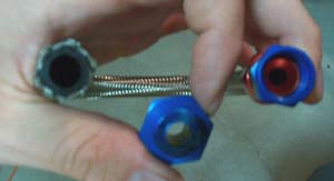
The -6, -8, -10 etc. are short for AN-6, AN-8, AN-10 where the AN stands for Army-Navy and they refer to the size of the tube, hose, or fitting. When divided by 16, the designation accurately depicts the outside diameter (OD) IF you are dealing with a metal tube. For instance, a -6 metal tube would have a 3/8" outside diameter (6/16 = 3/8) etc. However, we're not dealing with a metal tube but instead rubber hoses and the numbers don't carry the same meaning. For instance, here is how my AN-6 "Perform-O-Flex" hose measures:
AN-6 "Perform-O-Flex" hose OD = 35/64" (~.547")
AN-6 "Perform-O-Flex" hose ID = 11/32" (~.343")
AN-6 adapter (converts thread size) or union (same size thread both sides) ID = ~.292"
AN-6 "swivel seal tube hose end" (used on the ends of a AN-6 "Perform-O-Flex" hose) ID = ~.226"
In the picture from left to right, I measured the hose OD & ID, the union ID, and then the "swivel seal tube hose end" ID.
The hose dimensions listed above are the same between the -6 "Auto-Flex", "Perform-O-Flex", and "Speed Flex" brand of hoses, however, other brands of Earl's hoses measure differently. For instance, the -6 "Pro-Lite" hose measures .35" ID, .55" OD and the -6 "Super Stock" hose measures 3/8" ID, 5/8" OD. In short, be sure you know what you are getting before you put your hard earned cash down. Speak with an experienced sales representative to make sure the fittings you order work with the hose you selected etc.
For flow, we only care about the ID. With the -6 measurements listed for the "Perform-O-Flex" hose above, we can see that the smallest diameter is at the hose ends (swivel seal tube hose end) and is only ~.226". The stock 5/16" OD fuel supply line measures more than this at it's minimum dimension of ~.245" ID at the flared ends & ~.256" ID elsewhere. That is one reason I favor a -8 fuel feed hose over a -6. The smallest dimension on a -8 hose (at the swivel seal tube hose ends) came in at .375". Using the minimum measurements, the -8 hose will flow well over twice as much as the stock line whereas the -6 is worse than stock. When time permits I will actually calculate pressure drop between the stock supply line of known length and compare it to comparable -6 and -8 hoses. For a listing of available hoses, hose ends, and fittings/adapters, check out AN plumbing.com.
Restriction downstream the fuel rails is required to obtain a desired 43psi fuel rail pressure at idle (and higher under boost). Most of the restriction comes from the fuel pressure regulator, but some also comes from the small return line(s). Going to larger size lines after the fuel rail serves no purpose UNLESS you need larger lines to allow a "low" idle pressure of 43psi to be reached with a high flow fuel system (twin upgraded pumps etc.). My pump doesn't flow too much for the stock return line so I've kept it.
Back to my install:
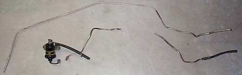
The first step was to remove all the stock equipment that wasn't going to be used. Most people leave the stock fuel supply line since it is a pain to remove but I wanted to route the new -8 line through the same guarded protection (more on this below). Cutting the stock supply line into three pieces made it easier to remove. The stock fuel filter, fuel rails, regulator, and supporting plumbing also came out. The only items still on my car from the original fuel system include the modified sending unit and the fuel return line.
After the stock hardware was removed, I began installing the fuel system starting with mounting the pump. AAM suggests placing the pump on the bottom side of the rear bumper. The lower it is placed, the easier it will receive fuel from the tank. If mounted higher than the tank, the pump life will be decreased unless you feed it with a second pump (preferably an in-tank unit). AAM claimed the fascia would not have to be removed, but it would have been difficult if not impossible to have a clean install without doing so. BTW, I did clean it up before putting it all back together.
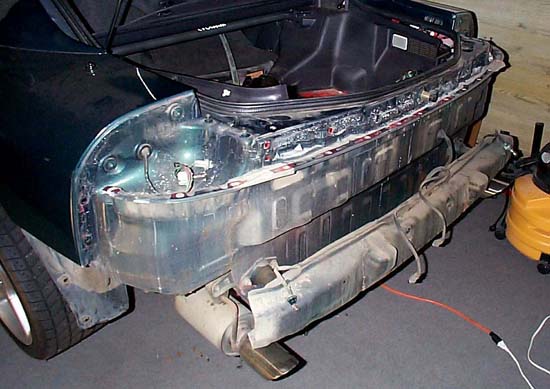
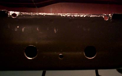
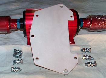
To fit the pump, I had to grind and cut away the down-turned edge of the bumper and drill a couple holes. I made the bracket out of 3/16" 6061 T6 aluminum. I considered isolating the pump to reduce NVH but opted to hard mount it to help it stay cool (better heat transfer). The pump mounts to the bracket at the four corners and then the bracket is bolted to the bumper at three locations.
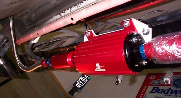
Here the pump is shown installed. The fascia will drape below and over the pump, protecting it from road debris but unfortunately trapping heat in.
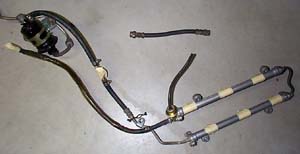
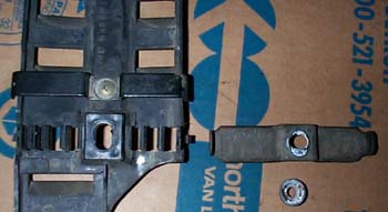
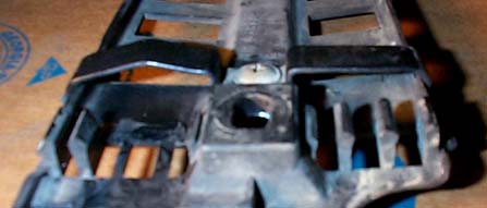
I didn't want to just zip tie the fuel line to the bottom of the car unprotected (especially with my 2" drop), so I removed the protective guard and modified it to accept the larger -8 hose. From left to right, the guard locates and protects the following 7 lines:
1) & 2) brake lines (one each for both rear wheels)
3) fuel supply line (the -8 line wouldn't fit in the original 5/16" space, hence the modification)
4) fuel return line
5) fuel tank vapor line
6) & 7) hydraulic lines for the rear steering
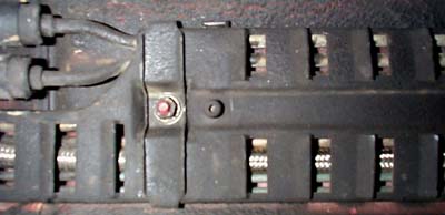
The left picture was taken before I modified the guard and the right, after. I ground away the plastic fingers on both sides of where the original supply line routed and bent the metal clip to allow the larger line to route through. This was repeated several times down the length of the guard.
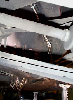
Here you can see some of the routing under the car; up and over the suspension similar to the stock routing. The -8 hose fit quite well in the modified guard.
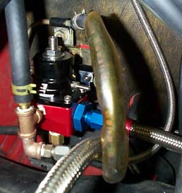
Onto the fuel pressure regulator (FPR). It took me a good week to collect all the correct parts but was well worth the trouble in the end. I decided to mount the FPR in the area left vacant by the OEM fuel filter. I used the fuel filter bracket and its rubber cushions to isolate the FPR from the firewall. I made the black bracket (pictured below) to allow everything to mount up. You may recall that the FPR as received from AAM had a steel braided -6 hose coming from it. I removed it since the -6 hose was too large (in my opinion) to connect to the factory return line and used the stock rubber return hose instead. Recall that the -6 hose ID is ~.343" while the stock return line has an OD of only .250", too much of a difference to reliably seal fuel. I don't want to chance spraying fuel in the engine bay.

The only short coming of this setup is adjusting the FPR. To adjust fuel line pressure, you need to loosen the lock down nut with a wrench, adjust FPR with an alan wrench and then tighten the lock down nut while holding the alan wrench steady. This is slightly more difficult when the FPR is sitting down out of clear view. However, I can clearly see the top of the FPR in the mounted location and can adjust it with one tool at a time (either a socket for the lock down nut or a alan head socket to adjust pressure). Because I cannot hold the alan position while tightening the lock down nut, it may take a couple tries to get the desired pressure, but how often do you need to change fuel pressure anyways?
The 3/8" rubber dump line will come in handy at the track when I need to purge my tank of street gas and fill-up with some race fuel. As you can see at the bottom right picture, I ended up having to add a 90 degree bend on the fuel pressure fitting so it would fit. The windshield wash bottle and battery tray have plenty of clearance to the FPR.

Will finish this page when the install is complete (still have to wire the pump).
since August 7th, 2002
Last Updated: 08/08/02 07:50 PM